
Sidebar
This is an old revision of the document!
Gmsh
Gmsh is an open source 3D finite element mesh generator with a built-in CAD engine and post-processor. Its design goal is to provide a fast, light and user-friendly meshing tool with parametric input and advanced visualization capabilities. Gmsh is built around four modules: geometry, mesh, solver and post-processing.
Gmsh allows a particularly good link between the mesh generator and the Lagamine solver.
Interface
Flowchart
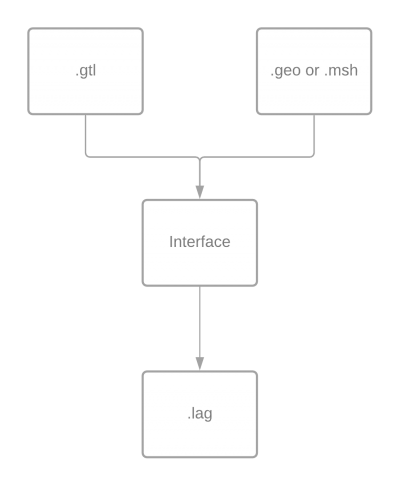
.txt file
This file contains all the specific informations that are in the '.lag' file, it corresponds to point:
- 1.Title
- 2.Control data of the program
- 5.Degrees of freedom (DOF) renumbering
- ???? 6. Duplicata nodes ????
- ???? 8. ID Matrix ????
- ???? 9-bis. Incremental forming ????
- 15. Constitutive laws
- 17. Elements → This section is a bit particular compare to the .lag file, before defining any type of elements, the word “ELEM” has to be read.
.geo file
It represents the geometry of the simulation, from this file it is possible to get the '.msh' file.
In Gmsh, it is possible to create entities that are called “Physical group”, each Physical group has a tag and a name. the first one is automatically given by Gmsh. The name will follow a convention to give the rest of the information that is not contained in '.txt' file, to compute the '.lag' file.
This convention is based on the Docuwiki numerotation:
3. Nodes coordinates
They are automatically extracted from the '.msh' file.
4. Gravity definition
| GRAVI (I2) | |
|---|---|
| 04 | |
| Axe definition (I2) | |
| 2 digits | (I2)=01 for x |
| 2 digits | (I2)=02 for y |
| 2 digits | (I2)=03 for z |
| Value definition (G10.0) | |
For example, to apply gravity along axis x, with a value of 9.81. The name of the Physical group has to be “04019.81” or “04019.81000000”.
7. DOF fixations
| FIXED (I2) | |
|---|---|
| 07 | |
| Axe definition (I2) | |
| 2 digits | (I2)=01 for x |
| 2 digits | (I2)=02 for y |
| 2 digits | (I2)=03 for z |
For more complex problem, it is possible to fix other DOF, it is possible to give a number between 01 and 09 which correspond to the DOF that has to be fixed.
9. Setting of the DOF to a non-zero value
| DISPL (I2) | |
|---|---|
| 09 | |
| Axe definition (I2) | |
| 2 digits | (I2)=01 for x |
| 2 digits | (I2)=02 for y |
| 2 digits | (I2)=03 for z |
| Value definition (G10.0) | |
Not yet developped.
10. Setting of the initial speeds in dynamics
| VELO0 (I2) | |
|---|---|
| 10 | |
| Axe definition (I2) | |
| 2 digits | (I2)=01 for x |
| 2 digits | (I2)=02 for y |
| 2 digits | (I2)=03 for z |
| Value definition (G10.0) | |
Not yet developped.
11. Setting of the initial accelerations in dynamics
| ACCE0 (I2) | |
|---|---|
| 10 | |
| Axe definition (I2) | |
| 2 digits | (I2)=01 for x |
| 2 digits | (I2)=02 for y |
| 2 digits | (I2)=03 for z |
| Value definition (G10.0) | |
Not yet developped.
12. Imposed nodal forces
| FORCE (I2) | |
|---|---|
| 12 | |
| Axe definition (I2) | |
| 2 digits | (I2)=01 for x |
| 2 digits | (I2)=02 for y |
| 2 digits | (I2)=03 for z |
| Value definition (G10.0) | |
13. Imposed nodal masses
Not yet developped.
14. Imposed nodal dampings
Not yet developped.
16. Fondations and tools
Not yet developped
17. Elements
BLZ3D is the only possibility for the moment.


